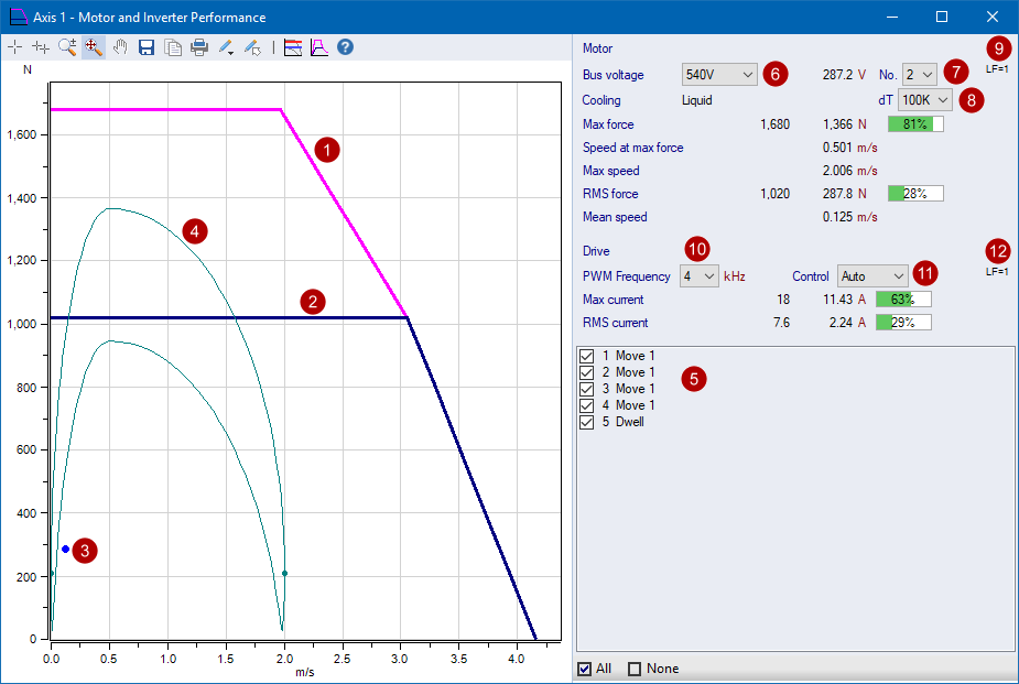
Motor Force vs Speed     

Motor rated peak force characteristic curve

Motor rated continuous force characteristic curve

Application RMS force

Application Profiles

  • Each motion segment is displayed
  • Segments where the start and end velocities are the same are shown as a dot

Show/Hide/Highlight Segments in the chart

  • When checked, the corresponding profiles are shown in the chart
  • When selected, the corresponding profiles are highlighted in the chart
  • Moves are grouped by their 4 Segments - Acceleration, Constant Velocity, Deceleration and Dwell
  • Select 1 or more Segments, then right-click for the option to Show or Hide the selected Segments

Motor Rated Peak Force Curve Bus Voltage

  • Display only. Not settable by the user.
  • The curve is automatically chosen by the program based on the power group nominal bus voltage
  • Click the drop down to see what other voltage curves are possible

Specify the number of motor primary parts


Motor Rated RMS Force Curve

  • Each rated force curve is defined with a temperature rise [K] wrt ambient temperature
  • Specify the temperature rise curve

Motor Load Factor

  • Effective load factor including ambient and elevation de-rating factors
  • Some vendors have additional factors that are also included. For the details of additional factors, hover the mouse over for the tooltip which provides additional details as needed

PWM Frequency

  • Specify the inverter PWM frequency
  • The higher the frequency usually results in lower rated peak and cont currents

Inverter Motor Control Mode

  • There are three options: 'Auto', 'No FW' & 'FW', where FW = Field Weakening
    • Auto:
      • 'Auto' is the recommended selection
      • If the motor data has both 'No FW' and 'FW' curves, then the program chooses the motor 'FW' curve
      • Else it choses the motor curve that is available for the selected motor
    • No FW: The user forces the use of the 'No FW' curve
    • FW: The user forces the use of the 'FW' curve

Drive Load Factor

  • Effective load factor including ambient and elevation de-rating factors


Drive Curves

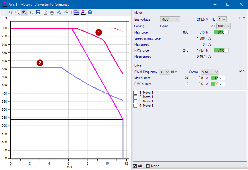
Select the 'Show Inverter Curves' toolbar button to display the inverter rated peak and continuous motor force

Inverter rated peak force characteristic curve

  • Solid line 0 - 6.3 m/s: Inverter rated peak current
  • Solid line 6.3 - 9.5 m/s: Infeed rated peak output power
  • Solid line 9.5 - 11.7 m/s: Bus voltage limit
  • Dotted line 6.3 - 11.7 m/s: Regen/Bleeder rated peak power

Inverter rated continuous force characteristic curve

  • 0 - 5.2 m/s: Inverter rated cont current
  • 5.2 - 11.7 m/s: Infeed rated cont power


Curves with Load Factor (LF)

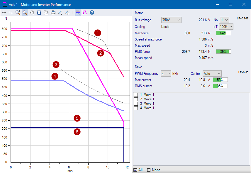
When the motor or drive are operating at a higher ambient temperature and/or elevation above sea level, an enviromental load factor (LF) is applied. In this case, two curves are shown, the original where LF = 1, and the effective curve with the LF.

Inverter rated peak force characteristic curve

Inverter rated peak force characteristic curve with the environment de-rating load factor (LF)

Inverter rated continuous force characteristic curve

Inverter rated continuous force characteristic curve with the environment de-rating load factor (LF)

Motor rated continuous force characteristic curve

Motor rated continuous force characteristic curve with the environment de-rating load factor (LF)


Related topics