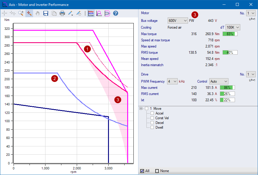
When the Motor and Inverter Performance form opens, initially
just the motor curves are shown in a 1 Quadrant view.
|

|
Motor rated peak torque characteristic curve
|
|

|
Motor rated continuous torque characteristic curve
|
|

|
Application RMS Torque
|
|

|
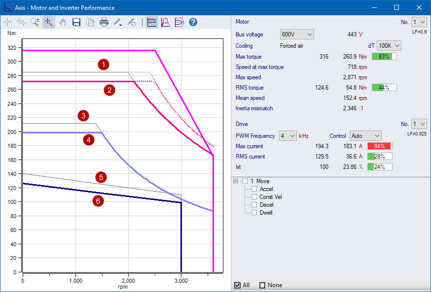
Application Profiles
- Each motion segment is displayed
- Segments where the start and end velocities are the same are
shown as a dot
|
|

|
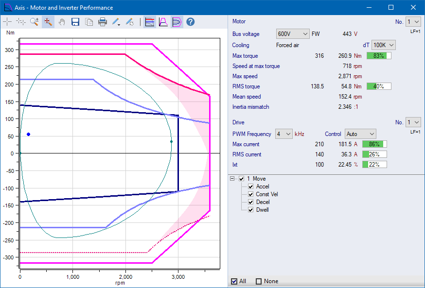
Show/Hide/Highlight Segments in the chart
- When checked, the corresponding profiles are shown in the
chart
- When selected, the corresponding profiles are highlighted in
the chart
- Moves are grouped by their 4 Segments - Acceleration, Constant
Velocity, Deceleration and Dwell
- Select 1 or more Segments, then right-click for the option to
Show or Hide the selected Segments
|
|

|
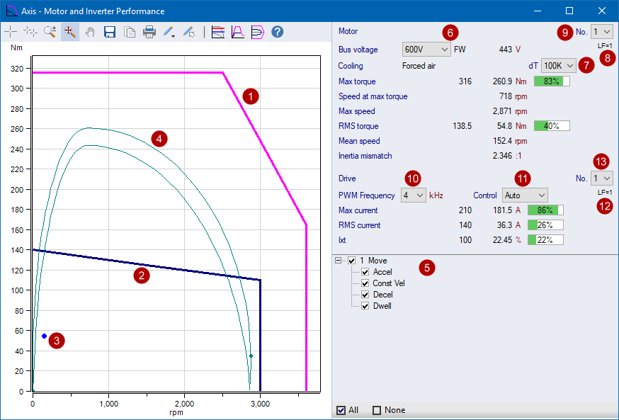
Motor Rated Peak Torque Curve Bus Voltage
- Display only. Not settable by the user.
- The curve is automatically chosen by the program based on the
power group nominal bus voltage
- Click the drop down to see what other voltage curves are
possible
- "FW" is shown when the motor rated peak field weakening (FW)
curve
- If FW is applied to the motor, the "FW" text is highlighed in
pink, same as the pink shaded FW zone in the chart
|
|

|
Motor Rated RMS Force Curve
- Each rated force curve is defined with a temperature rise [K]
wrt ambient temperature
- Specify the temperature rise curve
|
|

|
Motor Load Factor
- Effective load factor including ambient and elevation de-rating
factors
- Some vendors have additional factors that are also included.
For the details of additional factors, hover the mouse over for the
tooltip which provides additional details as needed
|
|

|
Specify the number of Motors in parallel
|
|

|
PWM Frequency
- Specify the inverter PWM frequency
- The higher the frequency usually results in lower rated peak
and cont currents
|
|

|
Inverter Motor Control Mode
- There are three options: 'Auto', 'No FW' & 'FW', where
FW = Field Weakening
- Auto:
- 'Auto' is the recommended selection
- If the motor data has both 'No FW' and 'FW' curves, then the
program chooses the motor 'FW' curve
- Else it choses the motor curve that is available for the
selected motor
- No FW: The user forces the use of the 'No FW' curve
- FW: The user forces the use of the 'FW' curve
|
|

|
Drive Load Factor
- Effective load factor including ambient and elevation de-rating
factors
|
|

|
Specify the number of Drives in parallel
|
 Motor Curves,
Data Panel & Segment Selection
Motor Curves,
Data Panel & Segment Selection
 Drive Curves,
Field Weakening Zone
Drive Curves,
Field Weakening Zone