Shared Bus - Multiple Supply, Multiple Internal Bleeders, Floating Bus |
Consider a typical 3-axis gantry robot application in a shared bus configuration with the following:
|
||
|
Line rectifier power module with an
uncontrolled bus Inverter module Internal bleeder module Shares the bus power for all axes |
|
|
Line rectifier power module with an uncontrolled bus Inverter module Internal bleeder module Shares the bus power for all axes |
|
|
Line rectifier power module with an uncontrolled bus Inverter module Internal bleeder module Shares the bus power for all axes |
|
|
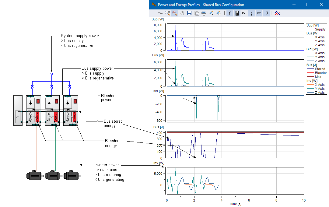
The total power the servo system draws or regenerates to the
supply connection |
|
The supply power to the bus from the infeed section of a
drive When there is more than one infeed, the user has the option to specify if the total infeed power is:
|
|
The bleeder power distributed to each enabled bleeder on the bus When there is more than one bleeder, the user has the option to specify if the total bleeder power is:
|
|
The stored bus energy at any point in time in the cycle |
|
The total energy dissipated by all bleeders in the system.
Shown to illustrate the amount of energy dissipated relative to the
total energy capacity of the bus. |
|
The inverter power to and from the motor |