Transformation |
A transformation can be used to simulate a transmission shaft, coupling, gear, belt and pulley, etc. The types of transformations and their graphics representations are:
|
|
None |
|
|
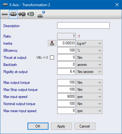
Coupling |
|
|
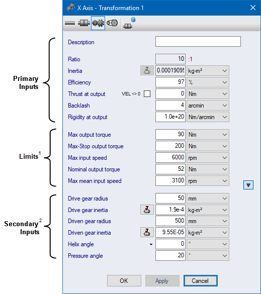
Gear |
|
|
Belt and Pulley |
Enter the coupling inputs directly, or select from the coupling database. The image below shows a coupling selected from the database.
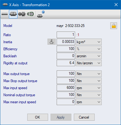
To unlock the inputs, click the unlock button at the top right of the form. Then all inputs can be modified.
Notes:
1 If a limit is
exceeded, an alarm is generated in System Check.
Notes:
1 If a limit is
exceeded, an alarm is generated in System Check.
2 When active, the Secondary Inputs are used to
calculate the Ratio and Inertia. Hence the Ratio and Inertia
inputs are locked when the Secondary Inputs are active.
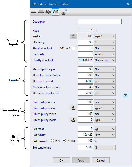
Notes:
1 If a limit is
exceeded, an alarm is generated in System Check.
2 When active, the Secondary Inputs are used to
calculate the Ratio and Inertia. Hence the Ratio and Inertia
inputs are locked when the Secondary Inputs are active.
3 The Belt Rigidity is used to calculate the rigidity at
the transformation output. Hence the Rigidity at Output input
is locked when the Belt Rigidity input is active.
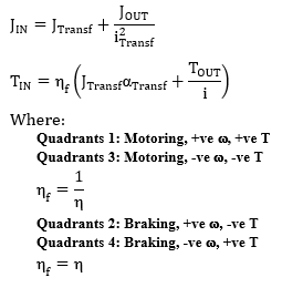
| Symbol | Description | Units |
|---|---|---|
| JIN | Total inertia at the transformation input | kg-m2 |
| JOUT | Inertia connected to the transformation output | kg-m2 |
| JTransf | Inertia of transformation at input | kg-m2 |
| TOUT | Torque at transformation output | Nm |
| TIN | Torque at transformation input | Nm |
| i | Reduction ratio | : 1 |
| aTransf | Rotational acceleration at transformation input | rad/s2 |
| h | Efficiency of transformation |


