News
Company News
SERVOsoft® News
- SEW EURODRIVE publishes product data for new PxG® economy line
Jun 16, 2026 - SERVOsoft v4.7.110 Released!
May 17, 2026 - SERVOsoft v4.7 Released!
Feb 16, 2026 - WITTENSTEIN cyber motor
publishes servo drive
solutions in SERVOsoft
Sep 29, 2025 - SERVOsoft Cloud Released!
May 23, 2025 - Energy Storage Modules
Tutorial
Jan 12, 2025
SERVOsoft News
SERVOsoft® v4.5 Released!
Apr 28, 2023
See highlights of the v4.4.208 release on Oct 31, 2022. For all release details, see the Revision Log.
What is +ve/-ve Phase Current Anyway?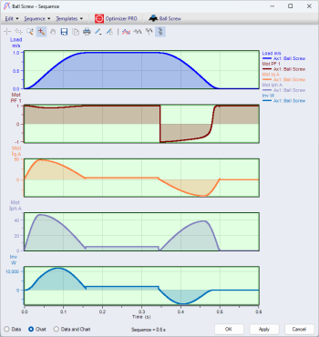
What is positive or negative motor phase current anyway? There is really no such thing. What matters is the power factor PF=COS(phi), and the sign of [PF] determines Motoring or Generating.
Many years ago, with relatively limited CPU & RAM resources, the motor phase current was the only current profile available in SERVOsoft. And also in the early days, there was no field weakening, such that Iph=Iq. So in those days, how to show Motoring or Generating? Positive/Negative current all in one profile. This is where it comes from. Today we don't have those limitations. Further, the motor model in SERVOsoft has evolved signficantly. The time has come to properly display the motor model profiles.
Starting in v4.5, the power factor [PF] and motor phase current [Iph] are as shown in the chart to the right, where, from top to bottom are Load Velocity, Motor PF, Motor Iq, Motor Iph and Inverter Power. Note how [PF] swings from positive to negative from 0.35s to 0.5s. Also note that [Iph] is always positive, and [PF] determines Motoring/Generating, confirmed by the [Iq] and Inverter Power profiles.
Supply Peak Power Optimization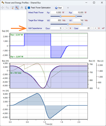
Supply Peak Power Optimization takes another big step forward with the option to add/subtract DC Bus [Cbus] and/or ESS [Cess] capacitance for quick scenario analysis.
Also added ability to find optimal [Cbus] and/or [Cess] to quickly find the optimal capacitance to minimize supply energy.
Supply Peak Power Optimization is a PRO version feature for Shared Bus Power Groups. It is located on the Power and Energy Profiles form.
Supply Peak Power Optimization minimizes the Supply Peak Power in Shared Bus applications by finding the best balance of energy storage, bus voltage range values [Vt0 - Vt1], and supply [Pps] and regen [Ppr] power limits.
In the ideal case, the Supply Peak Power is reduced to a low constant power over the entire cycle.
This is a common solution in the servo press industry, using a lot of bus storage, combined with managing the infeed supply power to reduce and smooth the mains supply. To see this powerful feature in action, see the tutorial Supply Peak Power Optimization of a Servo Press.
Added More Mechanisms in Parallel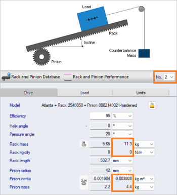
Added Mechanisms in Parallel (n>1) support for
- Ball Screws
- Rack & Pinions
- Rack & Gearbox Pinions
- Two Pumps
In addition to the following that already support n>1
- Linear Actuators
- Pumps
Note that the Payload and Thrust values are NOT multiplied by [n], where as the mechanism mass, inertia, rigidity and rated values are multiplied by n.
When n>1, "total" values for mass, inertia and rigidity are also shown.
Print Report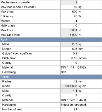
Smart enhancements to the Print Report including:
- Rack & Pinion mechanism now organizes Rack data under its heading, and Pinion data under its heading
- Shade all affected cells when more than 1 mechanism/transformation/motor/drive in parallel. Ie. n>1.
- Note that the Payload and Thrust values are not affected by n>1, where as the rack & pinion mass, inertia and rated force values are multiplied by n. So in the example to the right, n=2, and the rated max force for one rack & pinion is 3,030.5 N, and the total rated force for both racks is 3,030.5N x 2 = 6,061 N.
Rack & Pinion Combinations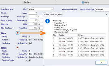
Added buttons to list all Racks or Pinions using the same combination parameters.
In the example to the right, all Racks using Module = 4, Helix angle = 0deg, Quality = 9, Material = DIN 1-1191 (C45E), Hardening = Soft. In the 2nd column are the rack lengths and bore holes that are different among them.
For those vendors that publish Rack & Pinion product data, this is a huge improvement that will help quickly isolate product data issues.
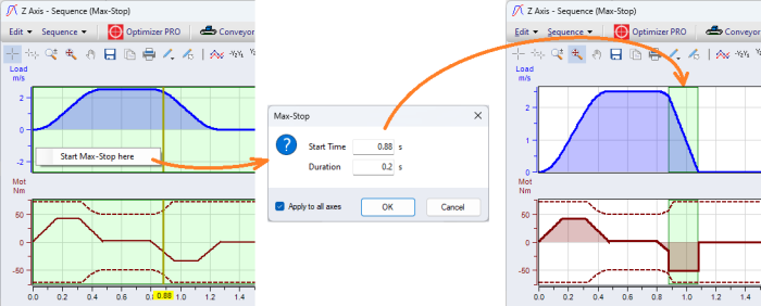
Max-Stop Mode
In the Sequence form when in Max-Stop mode, select the crosshairs and right-click and select
Start Max-Stop here to specify the Max-Stop ramp for the active axis or all axes in the Power Group.
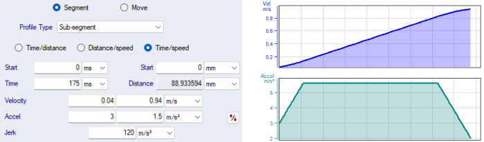
Sub-Segment now Fully Flexible Jerk-Linear-Jerk Ramp Segment
Extended profile type "Sub-Segment" to a fully flexible Jerk-Linear-Jerk ramp segment. Ie. Specify any portion of a standard Linear profile by specifying the Jerk, Start & End Velocity and Start & End Acceleration. Previously, only the linear, Start Jerk ramp or End Jerk ramp portion could be specified in one Sub-Segment. This exteneded capability allows for a continuous spline using a standard jerk profile without the need for polynomials.
Improved UI wrt Motor Field Weakening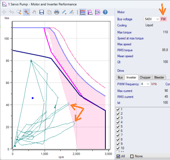
For PMSMs, when the Motor FW curve is used, now display "FW" beside the Bus Voltage value.
If field weakening is applied to the motor where the application profiles (green) cross over into the shaded FW zone, the "FW" text is highlighted in pink, the same colour as the motor FW zone in the chart. The same display is also done in the Main form beside the bus voltage drop down list.
Other New Enhancements
- Motor Models
- PMSM: Added database field [Ld] "Stator d-axis inductance" for PM salient machines
- Help: Added Phasor Diagrams for PMSM model
- Position Based Load
- Added ability to edit table data including add/delete rows, edit cell values
- Applies to Rotary and Slider Crank mechanisms
- Slider Crank:
- When motion defined at the Crank, added the option to specify "360deg Modulo"
- Linear Mechanism forms
- Moved the Incline input under the "Load" tab
- Applies to Conveyor, Ball Screw, Rack & Pinion, Cart, Slider Crank, etc.
- Ball Screw Mechanism
- Added Nut Roller Inertia input, used when the screw is rotating and the nut is stationary
- Added Screw Dynamic Load Rating [Ca] as an input under the Limits tab for a user-defined ball screw, thereby allowing for liftetime calculations for a user-defined ball screw
- Added drop down list for suggested mechanism efficiency values
- Ball Screw: 95% (typ. 70-95%)
- Roller Screw: 90% (typ. 70-90%)
- Lead Screw: 65% (typ. 35-65%)
- Added the following parameters to the Ball Screw performance data displayed on the Main form, consistent with the Performance form and Print Report
- Equivalent dynamic load
- Stroke
- Lifetime (distance)
- Lifetime (cycles)
- Lifetime (hours)
- Command Line Server and Command Line Print to File
- Added new variable [OperatingMode] to set the Operating Mode using the Command Line Interface. Previously, only Normal mode was supported.
- Added OperatingMode to XML report
- System Check
- When using Supply Peak Power Optimization with a passive infeed module (non-controlled DC bus) selected, added message "Passive Infeed selected. To optimize the Supply Peak Power, a 'Peak Power Shaving Module' is required to react to and limit the Mains Supply current. A Passive Infeed cannot target a bus voltage. Therefore, set Vt0=V0 and Vt1=V1, and no Regen Power Limit.".
- Database Utility
- Added extensive combinations checking for Racks, Pinions, FMax database tables. For those vendors that publish Rack & Pinion product data, this is a huge improvement that will help quickly isolate product data issues
- Added check if [DocPath] field is numeric with message "Invalid url". This will catch the scenerio where perhaps the [ProductZone] value was mistakenly entered in the [DocPath] column.
- For more details, see the Help: What's New in v4.5
Database
The SERVOsoft® database continues to grow with frequent updates, and now contains over 150,000+ products! Click here for a summary of the current products in the database.
If you are a vendor and want to add your products to the SERVOsoft® database and/or are interested in the Manufacturer Promotion Version, please contact us.